Last update: April 2023
PMI interoperability based on ISO STEP standards
The objective of this page is to give an overview of the PMI interoperability based on STEP. It is summed up according to the following paragraphs:
- Product and Manufacturing Information (PMI) scope
- ISO standards for Dimensional and geometrical product specifications
- PMI interoperability based on STEP
- PMI Semantic representation
- PMI Graphic presentation
- STEP Recommended practices for 3D PMI
PMI scope
Product and manufacturing information (PMI) is a type of Information needed to manufacture a product or component; its includes:
- Geometric Dimensioning and Tolerancing (GD&T)
- 3D text annotations
- 3D symbols
- User defined attributes
|
3D GD&T
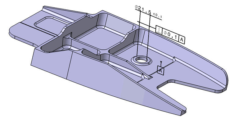
|
3D annotations

|
3D symbols

|
User defined attributes
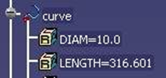
|
Figure 1: types of PMI
ISO standards for Dimensional and geometrical product specifications
These standards are under the responsibility of ISO TC 213 “Dimensional and geometrical product specifications and verification”. The table hereafter lists the main ISO standard relevant for the definition of the geometric dimensioning and tolerancing:
| ISO - Geometrical product specifications |
| ISO 286-1 - Geometrical product specifications : ISO code system for tolerances on linear sizes Part 1: Basis of tolerances, deviations and fits |
| ISO 286-2 - Geometrical product specifications : ISO code system for tolerances on linear sizes Part 2: Tables of standard tolerance classes and limit deviations for holes and shafts |
| ISO 1101 - Geometrical Product Specifications : Geometrical tolerancing Tolerances of form, orientation, location and run-out |
| ISO 2692 - Geometrical product specifications : Geometrical tolerancing - Maximum material requirement , least material requirement and reciprocity requirement |
| ISO 5458 - Geometrical product specifications : Geometrical tolerancing - Positional tolerancing |
| ISO 5459 - Geometrical product specifications: Geometrical tolerancing - Datums and datum-systems for geometrical tolerances |
| ISO 8015 - Geometrical product specifications : Fundamental tolerancing principle |
| ISO 10579 - Geometrical product specifications : Dimensioning and tolerancing of Non-rigid parts |
| ISO 14405-1 - Geometrical product specifications : Dimensional tolerancing Part 1: Linear sizes |
| ISO - Technical product documentation |
| ISO 16792 - Technical product documentation - Digital product definition data practices |
Table 1: List of the main ISO standards for Geometrical Product Specification (also called GD&T)
Nota: The American industry defines its own ASME standards for GD&T. They are similar to the ISO standards, but there are also some differences. They are not detailed in this page.
Nota: The standards for the verification will be described in a next version
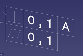
The following figure illustrates examples of geometric dimensioning & tolerancing symbols defined in the ISO Geometrical product specifications
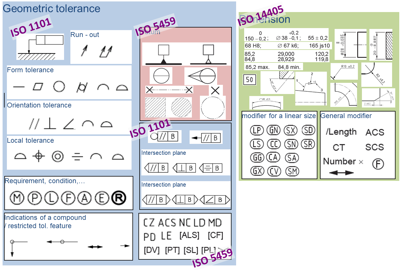
Figure 2: Overview of the ISO GPS standard
PMI interoperability based on STEP
Interoperability of Product and Manufacturing Information in STEP covers the capabilities of exchange between heterogeneous CAD-CAM systems, migration, long term archiving and Retrieval (EN9300 part 12x), and visualization of PMI information.
There are 2 main levels of functionalities of increasing complexity, and supporting different business needs:
- Interoperability of PMI “Graphic presentation”
- Interoperability of PMI “semantic representation”
Described hereafter.
PMI Graphic presentation
This captures the information displayed for PMI “as is”, by breaking down the annotations and symbols into basic geometry. This approach is the only one independent from the Representation, and is not Machine-interpretable.
|
Polyline Presentation: individual lines and arcs.
(Available in STEP AP203 and STEP AP214)
|
Tessellated presentation: set of triangle
(Available in STEP AP242)
|
The PMI graphic presentation is able to cover any type of annotation even if it is not compliant with the ISO and ASME standards.
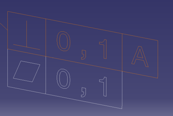
PMI Semantic representation
Describes the exchange of reusable, associative PMI in a STEP file. This information is by itself not visible in the 3D model, but a CAD system importing this file can use the Representation data to re-create the visible PMI. The representation approach also aims to pass PMI data on to downstream applications, such as CAM. Representation, simply stated is machine-readable/interpretable.
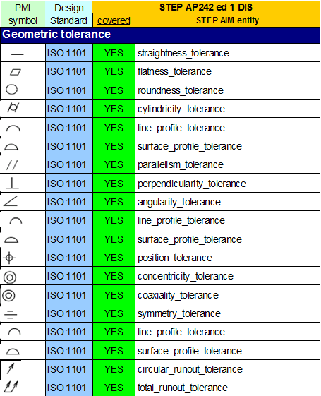
STEP covers a large set of the ASME & ISO GPS annotations. The following table illustrates the mapping of geometric tolerance in STEP AP242:
STEP Recommended practices for 3D PMI
http://www.cax-if.org/joint_testing_info.html#recpracs
For more details http://www.cax-if.org/vendor_info.php
 PMI interoperability